Showing posts with label geoprocessing. Show all posts

Monday, October 7, 2024

Scale and Resolution Effects on Spatial Data

What a last two weeks it has been this semester. Hurricane Helene threatened the area during the final week of September, shifting everyone's focus to preparation and expected impacts. The storm center passed approximately 90 miles to our west. While coastal impacts were severe, we were spared the brunt inland, even keeping electricity throughout the storm.

Followed that with a preplanned trip for AARoads to Puerto Rico. Then got started on the final module for GIS Special Topics and increased my time investment into the module leading into this past weekend as newly named tropical storm Milton formed in the Bay of Campeche. A Category 5 hurricane as of this writing, Hurricane Milton is expected to make landfall somewhere on the west coast of Florida on Wednesday or Thursday. While wind shear is eventually expected to weaken the storm, unlike Helene, Debby, Idalia and other storms, Milton is forecast to be a major wind event for inland locations. So anxiety levels are high!

The sixth module for GIS Special Topics investigates the effects of scale on vector spatial data and resolution on raster spatial data. The lab also covers spatial data aggregation and the concept of gerrymandering using GIS.

There are multiple meanings of scale to consider for Geographic Information Systems (Zanbergen, 2004).
  • as an indication of the relationship between units on a map and units in the real world. This is typically a representative fraction, which is commonly used with USGS Quads and GIS Maps in general.
  • to indicate the extent of the area of interest. Examples include spatial areas such as neighborhoods, cities, counties and regions.
  • to express the amount of detail or resolution. The resolution of a raster spatial dataset is the cell size, such as 10 meters for the Sentinel 2 blue, green and red spectral bands. This defines the scale of the data.
Scale in the Raster Data Model is straight forward represented by the resolution or cell size. A general rule is that a real world object needs to be at least as large as a cell in order to be recognizable.

Scale in the Vector Data Model also represents the amount of detail. While there is no single best method to express scale in vector data, a good indicator is the size of the smallest polygon or length of the shortest segment of a polyline.

When measuring the length of a complex shape, the total length depends on the smallest unit of the measuring tool. Where the units of a measuring tool decrease, the total length of the shape increases. More nodes and connecting segments result in longer shape lengths or area perimeters. The following images illustrate the differences in scale for the Vector Data Model.
Differing scales of Wake County, NC water flowlines
Water flowline vector data for Wake County, NC in different scales
Polygon vector data for Wake County, NC waterbodies at different scales
Waterbodies vector data for Wake County, NC in different scales

The properties of a Digital Elevation Model (DEM) depends upon what resolution is used. Higher resolution provides more detail. When measuring Slope, values decrease as the cell size increases and detail decreases. Higher detail results in steeper slopes. This effect applies to the full range of slopes regardless of steep areas of terrain (Zanbergen, 2004).
Scatterplot showing the relationship of Resolution vs. Slope in a DEM
Quantification of Resolution vs. Slope for a DEM in lab

The Modifiable Areal Unit Problem (MAUP) factors into deciding what scale to use for analysis of spatial data. MAUP is a complication with statistical analysis when quantifying aerial data. There are two facets of MAUP.

Scale Effect
The optimal spatial scale for analysis is generally not known, as there are multiple scales for analysis to be theoretically considered (Manley 2013). The results of data can be manipulated positively or negatively depending upon upon the size of the aggregation units used.

Zoning Effect
The method used to create areal units. This effect is the result of how spatial data is separated, such as the grouping of smaller areal units into less numbers of larger areal units (Dark & Bram 2007). Changing the grouping can manipulate the results of spatial analysis.

Part 2 of the lab conducting Linear Regression analysis of poverty statistics for Florida in U.S. Census data resulted in an example of MAUP. Different levels of aggregation convey different results:

Linear Regression Results based upon Congressional District

Linear Regression Results based upon Counties

Linear Regression Results based upon Zip Codes

Gerrymandering is the purposeful manipulation of a district shape with intentional bias (Morgan & Evans, 2018) or to affect political power (Levitt, 2010). Partisan gerrymandering takes place when the political party controlling the redistricting process draws district lines to benefit itself and restrict opportunities for opposition parties. While this maneuvering aims to increase inordinately the political power of a group (Levitt, 2010), the U.S. Supreme Court ruled that partisan-focused gerrymandering is not unconstitutional  (Morgan & Evans, 2018).

GIS can measure gerrymandering by the compactness in a number of ways. Compactness is the only common rule pertaining to redestricting that takes into account the geometric shape of the district. A district is considered compact if it has a regular shape where constituents generally live near each other. A circular district is very compact while a linear district is not (Levitt, 2010). 

Thanks to a discussion board post from our classmate Emily Jane, a method for determining compactness that I found easy to interpret is the Reock Score. Using this method, geoprocessing determines the minimum bounding circle around each polygon of a Congressional District. That is the smallest circle that entirely encloses the district. Reock scoring uses the ratio of the district area to the minimum bounding circle with the following equation R=AD/AMBC where AD is the area of the district and AMBC is the area of the minimum bounding circle. The score ranges from 0, which is not compacted, to 1, which is optimally compact.

Example of the Minimum Bounding Circle used with the Reock Score method
An example of the Minimum Bounding Circle around a District polygon for the Reock Score method 

Proceeded with the Reock Score analysis using the Minimum Bounding Geometry tool in ArcGIS Pro. This creates circular polygons for each record in the Congressional District dataset provided. With the minimum bounding circle area variable and the area value of the district, calculated the Reock score for every district. With a field added for the Reock Score, the worst "offenders" of gerrymandering based upon failing to have district 'compactness' from the provided dataset were determined.

Florida District 5 - 2nd worst gerrymandering 'offender'

North Carolina District 2 - the worst gerrymandering 'offender'

References

Zanbergen (2004). DEM Resolution. Vancouver Island University, Nanaimo, BC, Canada.

Manley, D. J. (2013). Scale, Aggregation, and the Modifiable Areal Unit Problem. In Handbook of Regional Science. Springer Verlag.

Dark, S. J., & Bram, D. (2007). The modifiable areal unit problem (MAUP) in physical geography. Progress in physical geography, 31(5), 471-479.

Morgan, J. D., & Evans, J. (2018). Aggregation of spatial entities and legislative redistricting. The geographic information science & technology body of knowledge, 2018(Q3).

Levitt, J. (2010). A Citizen's Guide to Redistricting. New York, NY: Brennan Center for Justice at New York University School of Law.


Sunday, September 22, 2024

Interpolation Methods - Tampa Bay Water Quality

There are numerous spatial interpolation methods used to generate surfaces in GIS. This is the prediction of variables at unmeasured locations based upon sampling of similar variables at known locations or true points. Related, spatial prediction is the estimation of variables at unsampled locations based partly on other variables and a collective set of measurements. Comprised of spatially continuous data, surfaces could be topographic, a measure of air pollution, soil moisture, air temperatures and population density among others (Bolstad & Manson, 2022).

A number of factors can affect the performance of spatial interpolation methods. Some of these factors are data accuracy, temporality of the data, sampling design, sample spatial distribution, the presence of abnormal values or outliers, and the correlation of primary and secondary variables (Hu, 1995, Li & Heap, 2014).

Deciding upon the best interpolation method is not always a straight forward process. Methods often work well for a specific data set because of inherent assumptions and algorithm design for estimation. Different interpolations methods applied to the same data set may produce desired results for one study objective but not another (Hu, 1995).

Module 5 for GIS Special Topics performs interpolation analyses for Tampa Bay water quality data. Specifically four methods are used for the estimation of Biochemical Oxygen Demand (BOD) in milligrams per liter variables for Tampa Bay. A point feature class of BOD sample locations is provided and the study area is all of Tampa Bay, Old Tampa Bay and Hillsborough Bay. A statistical analysis of each is compared in an effort to determine which derived surface best describes water quality.

The first interpolation method implemented for the Tampa Bay water quality analysis is Thiessen Polygon. This method was the easiest to interpret. It aggregates the point dataset within the study area to polygons with one per point, which is referred to as a centroid. All estimated points within the Thiessen polygon (proximal zone) are closer in value to the associated centroid than any other centroid in the overall analysis.

The Thiessen Polygon method is optimal when there is no uniform distribution of the sample points. The method is applicable to environmental management (Wrublack et. al, 2013).

Thiessen Polygon interpolation of Tampa Bay water quality
The Thiessen Polygon raster with an output cell size of 250.

Previously discussed in the Isarithmic Mapping lab in Computer Cartography, the Inverse Distance Weighting (IDW) spatial interpolation method estimates values using the values of sample points and the distance to nearby known points (Bolstad & Manson, 2022). Values closer to a location have more weight on the predicted value than those further away. The power parameter in the mathematical equation of the method determines the weighting, which decreases as the distance increases. When the power parameter increases, a heavier weight is applied to nearby samples, which increases their influence on estimation (Ikechukwu, 2017).

The IDW method assumes that the underlying surface is smooth. It works well with regularly spaced data, but cannot account for the spatial clustering of sample points (Li & Heap, 2014).

Tampa Bay water quality estimates from the IDW method
The IDW raster for water quality. The power parameter was 2 and output cell size of 250.

Spline interpolation uses a mathematical function to interpolate a smooth curve along a set of sample data points with minimal curvature. Polynomial functions calculate the segments between join points. These accommodate local adjustments and define the amount of smoothing. The method is named after splines, the flexible ruler cartographers used to fit smooth curves through fixed points (Ikechukwu, 2017).

The performance of Splines improves when dense, regularly-spaced data is used (Li & Heap, 2014). The method is very suitable for estimating densely sampled heights and climatic variables (Ikechukwu, 2017).

The lab uses the options of Regularized and Tension for the Spline geoprocessing tool in ArcGIS Pro. This changes the weight parameter, where higher values in Regularized splines result in smoother surfaces. A weight of zero for the Tension spline option results in a basic thin plate spline interpolation. This is also referenced as the basic minimum curvature technique.

Tampa Bay water quality - Regularized Spline interpolation
Estimated Tampa Bay water quality - Regularized Spline Interpolation Method

Tampa Bay water quality - Tension Spline Interpolation Method
Estimated Tampa Bay water quality - Tension Spline Interpolation Method

References:

Bolstad, B., & Manson, S. (2022). GIS Fundamentals – 7th Edition. Eider Press.

Hu, J. (1995, May). Methods of generating surfaces in environmental GIS applications. In 1995 ESRI user conference proceedings.

Li, J., & Heap, A. D. (2014). Spatial interpolation methods applied in the environmental sciences: A review. Environmental Modelling & Software, 53, 173-189.

Wrublack, S. C., Mercante, E., & Vilas Boas, M. A. (2013). Water quality parameters associated with soil use and occupation features by Thiessen polygons. Journal of Food, Agriculture & Environment, 11(2), 846-853.

Ikechukwu, M. , Ebinne, E. , Idorenyin, U. and Raphael, N. (2017) Accuracy Assessment and Comparative Analysis of IDW, Spline and Kriging in Spatial Interpolation of Landform (Topography): An Experimental Study. Journal of Geographic Information System, 9, 354-371. doi: 10.4236/jgis.2017.93022.

Monday, August 5, 2024

Corridor Suitability Analysis - Coronado National Forest

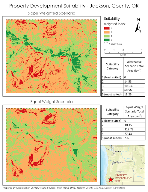
The final scenario for the lab of GIS Applications Module 6 is to determine a potential protected corridor linking two areas of black bear habitat in Arizona's Coronado National Forest. Data provided included the extent of the two existing areas of known black bear habitat, a DEM, a raster of land cover and a feature class of roads in the study area. Parameters required for a protected corridor facilitating the safe transit of black bear included land use away from population and preferably with vegetation, mid level elevations and distances far from roadways.

Geoprocessing flow chart for Scenario 4

The initial geoprocessing in our Corridor Suitability Analysis reclassifies the DEM and landcover rasters into suitability rasters using predetermined scales. The development of a suitability raster for the roads feature class commenced with creating a multi-ring buffer feature class, and then converting the derived polygons into a suitability raster using the Reclassify tool.

Reviewing the previous scenarios on outputting buffers from a polyline, I also ran the Euclidean Distance tool on the roads feature class. The succeeding output raster was then Reclassified using the distance suitability values that rank higher proximities with lower values. The results mirrored those using the Multi-Ring Buffer tool:
Suitability Raster for proximity to roads using the Euclidean Distance tool
The suitability raster for the distance to roads derived from the raster output from the Euclidean Distance tool.

With suitability raster files finalized for elevation, landcover and proximity to roads, we can proceed with the analysis using the Weighted Overlay tool. The objective is to generate a cost raster using the integer scale of 1 through 10, based upon the influence percentages of 60% for land cover, 20% for elevation and 20% for distance to roads.

The result shows the highest suitability score for mid level elevations representative of undeveloped forest land that mostly avoids roads. Low level elevations represented by urban areas, agriculture and barren land factor into low suitability areas:
Weighted Overlay raster of Suitability areas
Weighted Overlay raster with the values of 1-10 where lighter colors represent lower suitability scores

Utilizing the Weighted Overlay raster, a cost surface raster is generated by using the Raster Calculator geoprocessing tool. The cost surface values were obtained by inverting the suitability model so that higher habitat suitability values translated into lower travel costs:
Cost Surface Raster
Cost Surface raster where the darker colors represent higher costs

With the Cost Surface raster, the Corridor Suitability Analysis continues with the Cost Distance tool run on the two Coronado National Forest black bear habitat area feature classes. This outputs Cost Distance and Cost Distance Backlink Rasters.
Coronado N.F. Destination Raster - 1st feature class
The cost distance raster for the northeastern unit of Coronado N.F.
Coronado N.F. Destination Raster - 2nd feature class
The cost distance raster for the southwestern unit of Coronado N.F.

Together the two cost distance rasters for Coronado National Forest are the parameters for the Corridor geoprocessing tool, which generates the Least-Path Corridor raster. The threshold value for determining the best corridors was subjective, so I went with percentages used in the previous scenario, where the minimum destination cost value multiplied by 1.05 represented the optimal corridor. Chose a color scheme based upon the ColorBrewer web site.

Black Bear Suitability Corridor Analysis
The Least-Path Corridor for a protected Black Bear Corridor between Coronado National Forest units


Thursday, August 1, 2024

Suitability Modeling with GIS

Module 6 for GIS Applications includes four scenarios conducting Suitability and Least-Cost Path and Corridor analysis. Suitability Modeling identifies the most suitable locations based upon a set of criteria. Corridor analysis compiles an array of all the least-cost paths solutions from a single source to all cells within a study area.

For a given scenario, suitability modeling commences with identifying criteria that defines the most suitable locations. Parameters specifying such criteria could include aspects such as percent grade, distance from roads or schools, elevation, etc.

Each criteria next needs to be translated into a map, such as a DEM for elevation. Maps for each criteria are then combined in a meaningful way. Often Boolean logic is applied to criteria maps where suitability is assigned the value of true and non suitable is false. Boolean suitability modeling overlays maps for all criteria and then determines where all criterion is met. The result is a map showing areas suitable versus not suitable.

Another evaluation system in suitability modeling use Scores or Ratings. This scenario expresses criterion as a map showing a range of values from very low suitability to very high, with intervening values in between. Suitability is expressed as a dimensionless score, often by using Map Algebra on associated rasters.

Scenario 1 for lab 6 analyzes a study area in Jackson County, Oregon for the establishment of a conservation area for mountain lions. Four sets of criterion area are specified. Suitable areas must have slopes exceeding 9 degrees, be covered by forest, be located within 2,500 feet of a river and more than 2,500 feet from highways. 

Flow Chart outlining the Suitability Modeling
Flowchart outlining input data and geoprocessing steps.

Working with a raster of landcover, a DEM and polyline feature classes for rivers and highways, we implement Boolean Suitability modeling in Vector. The DEM raster is converted to a slope raster, so that it can be reclassified into a Boolean raster where slopes above 9 feet are assigned the value of 1 (true) and those below 0 (false). The landcover raster is simply reclassified where cells assigned to the forest land use class are true in the Boolean.

Buffers were created on the river and highway feature classes, where areas within 2,500 feet of the river are true for suitability and areas within 2,500 feet of the highway are false for suitability. Once the respective rasters are converted to polygons and the buffer feature classes clipped to the study area, a criteria union is generated using geoprocessing. The suitability is deduced based upon the Boolean values of that feature class and selected by a SQL query to output the final suitability selection.

We repeat this process, but utilizing Boolean Suitability in Raster. Using the Euclidean Distance tool in ArcGIS Pro, buffers for the river and highway feature classes were output as raster files where suitability is assigned the value of 1 for true and 0 for false. Utilized the previously created Boolean rasters for slope and landcover.

Obtaining the suitable selection raster with the four rasters utilizes the Raster Calculator geoprocessing tool. Since the value of 1 is true for suitability in the four rasters, simply adding the cell values for all result in a range of 0 to 4, where 4 equates to fully suitable. The final output was a Boolean where 4 was reclassified as 1 and all other values were assigned NODATA.

Scenario 2 determines the percentage of a land area suitable for development in Jackson County, Oregon. The suitability criteria ranks land areas comprising meadows or agricultural areas as most optimal. Additional criterion includes soil type, slopes of less than 2 degrees, a 1,000 foot buffer from waterways and a location within 1,320 feet of existing roads. Input datasets consist of rasters for elevation and landcover, and feature classes for rivers, roads and soils.

Flowchart showing data input and processes to output a weighted suitability raster
Flowchart of the geoprocessing for Scenario 2

With all five criteria translated into respective maps, we proceed with combining them into a final result. However with Scenario 2, the Weighted Overlay geoprocessing tool is implemented. This tool utilizes a percentage influence on each input raster corresponding to the raster's significance to the criterion. The percentages of each raster input must total 100 and all rasters must be integer-based.

Cell values of each raster are multiplied by their percentage influence and the results compiled in the generation of an output raster. The first scenario evaluated for lab 6 includes an equal weight scenario, where the 5 raster files have the same percentage influence (20%). The second scenario assigned heavier weight to slope (40%) while retaining 20% influence to land cover and soils criterion, and decreasing the percentage influence of road and river criterion to 10%. The final comparison between the two scenarios:

Land Development Suitability Modeling - Jackson County, OR
Opted to symbolize the output rasters using a diverging color scheme from ColorBrewer.

Wednesday, June 12, 2024

Automating Geoprocessing with Python

Moving into Module 5, our assignment this week consists of writing a Python script to automate geoprocessing tasks. We were provided a dataset with several Alaska and New Mexico feature classes and the task of copying them into a newly created file geodatabase (fGDB). Working with lists and dictionaries, our script also implements several functions including ListFeatureClasses, Describe, and SearchCursor. Our end task was to output a dictionary (a Python list with pairs of keys:values) of New Mexico county seats.

As an aside, I always like working with data from places I have visited. Including an Albuquerque airport stop in 2007, I've been to New Mexico four times. I also updated the Universal Map Group Wall Map for Albuquerque as one of my projects in 2008.

Tijeras, New Mexico in 2017
I-40 west ahead of Tijeras from my trip to New Mexico in 2017.

The ListFeatureClasses() function returns a list of feature classes in the current workspace. This list can be stored in a variable to be used with subsequent functions. Part of the ArcPy package, the Describe() function returns a Describe object which includes properties of a feature class such as data type, geometry type, basename, etc.

Using the Describe function on the variable with the feature class list allows a property, such as the basename, to be used as part of the CopyFeatures() function in the Data Management toolbox. This function copies input feature class features into a new feature class. With a for loop, we used this to populate our newly created file geodatabase (fGDB) with a concatenation of a variable for the output environment, the name of our created fGDB and the basename property of each feature class.

The Flow Chart for this week's Lab assignment
The program flowchart for this week's Lab assignment

While the term cursor to me references the blinking vertical line in this word processor, it has a separate meaning in computer programming. Cursor is a database technology term for accessing a set of records in a table. Records in a table are referred to as rows. Iterating over the row of a table, the three cursors in Python are as follows:

  • Search Cursor - this function retrieves specific rows on the basis of attribute values. This is similar to performing a SQL query.
  • Insert Cursor - this function adds new roads to a table, which can in turn be populated with new attribute values.
  • Update Cursor - this function modifies the attribute data of existing rows or deletes rows from the table.
Each type of cursor is created by corresponding class of the arcpy.da.module. The cursor object accessed row objects, returning a tuple of field values in an order specified by the field names argument of the function. The cursor iterates over all table rows but using only specific fields as needed.

Cursors support with statements, which have the advantage of executing regardless of whether the cursor finished running successfully and completing without a data lock. A data lock ensues otherwise is a cursor is not deleted with a del statement. The data lock prevents multiple processes from changing the same table simultaneously.

With statements also incorporate SQL queries as the where_clause optional parameter in the SearchCursor syntax. SQL queries find records in a database table based upon specific criteria selecting data WHERE specific conditions occur. I often use SQL queries when updating the database for the main AARoads pages and also occasionally with the Simple Machines Forum database on the site.

The Lab assignment specified using the SearchCursor on the feature class of point data for cities in the state of New Mexico. The search criteria fields were the city NAME, the city FEATURE type and the 2000 Census population data (POP_2000). I found that assigning the SearchCursor output as variables made formatting the print statement vastly easier and cleaner looking codewise.

The biggest challenge I had was populating the dictionary with the county seats. I eventually incorporated the process in the for loop of the SearchCursor with statement. Used the W3Schools web site to narrow down the code to use, and with the previous variables, creating the dictionary was simple.

Looking at the example output included in the Lab assignment PDF, I opted to expand upon the formatting. Being the county collector that I am, I incorporated the COUNTY name field so that the output listed the associated county with each seat. Furthermore after discovering that three of the entries lacked population data, I implemented an if statement. The missing data values showed -99999. Being that it was an integer, I first cast that as a string, and then reassigned the population variable to read "not available".
Output showing completion of Geoprocessing tools
Collage of screen shots showing the output of the Module 5 Python Script


Wednesday, June 5, 2024

Geoprocessing with Python scripts and Models in GIS

The two main focuses of this week's Lab assignment in GIS Programming was an introduction to Model Builder in ArcGIS Pro and coding a geoprocessing script from scratch. The lessons show that Geoprocessing Tools can be run solely with Python scripts and the process be automated using models. Both use the ArcPy package, which contains several modules and other elements that add functionality to Python.

Geoprocessing is a series of actions performed on geographic data where there is an input or multiple inputs, a process or task, and then an output of data. There are two general categories of geoprocessing tools in ArcGIS Pro. There are the system or built-in tools created by ESRI. Then there are custom tools, including models and scripts, created by a user or a third-party.

Model Builder is used to run a sequence of tools to obtain a desired result. The application uses four elements: data variables which reference data on disk, value variables provided in formats such as linear units, connectors and tools. Model Builder uses a GUI interface and layout with some similarities to the program flowcharts designed in previous modules. The model elements are color coded to aid in their classification.

ArcGIS Pro Model Builder
The model I developed showing the automation of using three Geoprocessing tools

With sample data provided, the model created for Module 4 took a polygon layer of soils and clipped it to a polygon layer of a basin. The extracted section of the soils feature class was then filtered to select only parcels that were deemed unsuitable for farming. That subset of the soils data was then removed from previously created soils layer including only areas within the original basin.
Polygon feature class showing soils suitable for farming
Output layer of suitable soils for farming

If you had this kind of data over a large area, such as a county or state, rerunning this model for specific locations could save a significant amount of time. ArcGIS Pro can also export this model as a stand alone Python script. The only caveat is making sure the workspace environment, the default location for the files being processed, is set. This typically means using more explicit information such as full file paths.

What is an environment? Our textbook describes them as "essentially hidden parameters that influence how a tool runs." Environments are properties of the env class in ArcPy. Part of object-orientated programming (OOP), classes can be used to create objects, which in turn has properties and methods that can be used. Classes are often implemented to avoid using long and complicated strings in code. The OOP concept is still somewhat fuzzy to me, but  it is becoming more clear with continued use of Python .

Using Python code to perform geoprocessing tasks was not as difficult as anticipated. The three tasks to complete started with a point feature class of hospitals as the input data. Geoprocessing tools first add field values for X and Y based upon the coordinate system of the dataset. The second created a 1,000 meter buffer around each point while the last dissolved the individual buffers as a single feature in a completely separate feature class.

Geoprocessing Python Script Flow Chart
Flowchart showing the general behavior of the Python script

Approached writing this script by researching the syntax for the three geoprocessing tools. With a basic understanding of required parameters and optional parameters, coding was fairly straight forward. Trying out some of the syntax options, I hard-coded parameters such as the input feature layer name while assigning a variable for another function argument.

I also tried out separate nomenclature for calling the tools. Tools can be called by its function such as arcpy.<toolname_tollboxalias>(<parameters>) or the toolbox as a module followed by the tool as a function as arcpy.<toolboxalias>.<toolname>(<parameters>. The main difference is the use of an underscore or dot between the tool name and tool alias.

Used comments on most lines of the script so I can return to it for reference. With the final line of code compiled, I ran the script and encountered an error referencing the incorrect parameters for the Dissolve tool. I then implemented a try-except statement and quickly identified that I forgot to add a comma between the in_features and out_feature_class parameters. With that, the script ran successfully!

Successful run of a Python script running Geoprocessing Tools


Friday, October 13, 2023

Bobwhite Manatee Transmission Line Analysis - Final Project

The final project for GIS4043/Intro to GIS conducts analysis on the Bobwhite Manatee Transmission Project in Southwest Florida. Part of the Florida Power & Light (FPL) infrastructure, the 24.5 mile long transmission corridor was developed to serve growing areas of eastern Manatee and Sarasota Counties, including Lakewood Ranch. Additionally the new line offers redundancy during hurricanes, something tested since it was completed with Hurricane Irma in 2017 and Hurricane Ian in 2022.

GIS analysis was used in part to determine the optimal location for the proposed transmission corridor. The design of the route took considerations for reducing impacts on sensitive or protected conservation land, avoiding schools and daycares, and providing a buffer from existing homes. Community input factored heavily with the corridor ultimately selected. FPL also worked with Schroeder-Manatee Ranch (SMR), the developer of the Lakewood Ranch community, to select a route that preserves the natural beauty of the area.

The study area was 273 square miles wide, mostly spread across central Manatee County along with a portion of northern Sarasota County. The project was announced by FPL in June 2006. With input from a community advisory panel, open house events and surveys mailed to area residents, FPL developed formal plans, which were unveiled in October 2006.

The Bobwhite Manatee Transmission Line project was eventually certified by the Florida Department of Environmental Protection. It subsequently cleared the Transmission Line Siting Act and was approved by the Florida Cabinet and Governor on October 28, 2008. Construction was anticipated to begin in 2010. It ultimately did in 2013, following additional compromises made between FPL, SMR, area homeowners and Taylor & Fulton, an area agricultural group.

Our project looks at four criteria analyzed by GIS for the selection of a preferred corridor for the transmission line. The first objective considered the number of homes and overall properties within proximity of the corridor.

Using the buffer geoprocessing tool, a 400-foot buffer was created around the preferred corridor of the planned transmission line. A feature class locating all homes within the corridor and associated buffer was next created with heads-up digitizing using 2006 aerial photography. With all visible homes added to GIS, running the "select by attribute" geoprocessing tool on created fields that indicated if a home was either within the corridor or within the 400-foot buffer, provided the totals. A map output of the homes and parcels intersecting the corridor:


The transmission line that was eventually built comes no closer to 600 feet from an existing home. No doubt GIS aided in achieving this buffer.

The second objective of GIS with the Bobwhite Manatee Transmission Line project was a simple one. Are their any schools or daycare centers within the preferred corridor, or the associated 400-foot buffer? Some work outside GIS was required to analyze this, as point feature classes for schools and daycares did not exist.

Researching area schools with the Department of Education website, and other websites for daycares falling within zip codes that crossed the preferred corridor, lists were compiled in Excel. These were in turn geocoded into GIS, using more recent street centerline files to complete address matching for automating the location process.

With school layers compiled, the select by attributes geoprocessing tool determined that no schools or daycare centers were within the preferred corridor or buffer:

That fact that FPL avoided all schools and daycares certainly reduced community opposition to the overall project.

Moving on with the analysis, environmental impacts to both conservation areas and wetlands was considered. National Wetlands Inventory (NWI) and Florida Managed Lands data were provided. The question to be answered is how many acres of each land type was within the preferred corridor?

For wetlands, the NWI feature class was clipped within the preferred corridor polygon. The result were records for uplands and two wetland types, with the Shape Area field providing the areas in square meters. After converting the values into acres, calculating the total acres of uplands and wetlands was easily achieved using the Summary Statistics geoprocessing tool.

Conducting spatial analysis on the conservation areas, a different approach was taken using the Select by Location geoprocessing tool with the Intersect relationship. This extracted all polygons in the conservation land feature class that were within the preferred corridor into a new feature class. The resulting data revealed that relatively small portions of a conservation easement, watershed and state park were in the preferred corridor:


The final objective analyzed by GIS was to estimate the total length of the then-future transmission line, and to use that figure in an equation to estimate construction costs. This was a straightforward process using the Polygon to Centerline geoprocessing tool.

However one data discrepancy occurred with the creation of the centerline feature class. The centerline split into separate branches within the triangular shaped wedge at the south end of the preferred corridor. I considered these to be outliers when it came to the determining the overall length of the transmission line.

One option was to take an average of the length between the two and consider adding that to the main centerline vector. Another option was to omit them entirely, as the project included constructing the Bobwhite Substation within that wedge shaped area.

GIS analysis determined an estimated total length of 24.76 miles. An East County Observer news article on the Bobwhite Manatee Transmission Line in 2013 referenced the line being built at the time as 24.5 miles in length. So this was a pretty good result from GIS.

Living in Bradenton from June 2013 to April 2015, I drove by this project several times without knowing much about it. While doing photography for AARoads, I captured work in progress along State Road 64. Looking back at the photos, what was built was a 230kV single circuit transmission line on a steel tubular pole. Using the equation provided with the GIS project documents, that resulted in a rate of $1.1 million per mile. The $27.236 million I calculated was well above the $20 million cost reported in the East County Observer article.

In conclusion, it appears that FPL designed the Bobwhite Manatee Transmission Line with a priority in the feedback from the community. The route was designed to follow existing right of way for several major highways. Using that space instead of a new corridor, the impacts to protected lands was minimized. Beside one home that was eventually demolished to make way for the Bobwhite Substation, it appears as if most existing homes were avoided by the power line.

Wrapping things up, beyond the deliverables posted above, we were tasked with creating a Power Point Slide Show presentation and accompanying transcript. Both are uploaded to my Google Drive:

Friday, September 22, 2023

Geocoding Data - Manatee County Schools

This week's lab project introduced me to Geocoding within ArcGIS Pro and some Excel spreadsheet tactics used to prepare the data for it. The focus of this project is to extract the geographic location for Manatee County Schools from the list posted on the Florida Department of Education web site.

Started the lab with a simple copy and paste of the schools list, which includes 84 entries ranging from Charter Schools to Colleges. Added these to an Excel spreadsheet and proceeded to format the data for processing by ArcGIS Pro. The end result were data columns including the school's name, street address, city and zip code.

With the Excel spreadsheet saved as a .CSV file, proceeded into ArcGIS Pro with downloaded TIGER line shapefile data for Manatee County, Florida. The schools list data was then imported into a table.

Geocoding in ArcGIS Pro utilizes either an X/Y location using latitude/longitude, or in the case here, with an address location. First, we needed to compile an address locator file for Manatee County. Using the Create Locator tool, parameters on the TIGER line fields were set for the street name, zip codes right and left for the side of a street segment, and similarly left and right house number ranges. The process ran on the Manatee County line file, creating the Address Locator file needed for the Geocode Table tool.

The Geocode Table tool cross references the Schools input table with the Address Locator file. With our three columns of location data from the original Excel sheet, selected Address, City and Zip as the Data for the Locator Field within the tool. The process creates a geocoded point file of all school locations.

Of the 83 entries within the Schools table, all but four were matched. Those needed further analysis to be located.

One of the entries was located simply by abbreviating "Street" in the address field to "St". Based upon Florida State Road addresses, the remaining three were manually placed by researching their location.

The data entry for Carlos E. Haile Middle School used Fl 64 as the address street name. A problem with this is that often numbered routes have formal names that are used for postal addressing. Furthermore, while FL 64 implies Florida State Road 64, FDOT and other government agencies often instead use "SR" on signing and for addressing.

Two of the schools were addressed as "State Route 70" or "SR 70". The TIGER line data uses 53rd Avenue E in the FULLNAME field for the segment of SR 70 where the schools are actually located. So those schools are misplaced. Contrary to that, two of the original unmatched schools are located along SR 64 in Lakewood Ranch, which the TIGER line data references incorrectly as Manatee Avenue. Manatee Avenue is the formal name for SR 64 within Bradenton. East of there, State Road 64 is the formal name for SR 64 in unincorporated Manatee County.

Data quality is definitely a concern for when it comes to Geocoding. Whether it be an inaccurate address or missing data, these can result in potentially time consuming problems.

Published the final geoprocessed data, showing Manatee County populated with the various school locations, on the webmap at https://pns.maps.arcgis.com/home/item.html?id=c66a66146c024cec9064604c851b0f23. Edited the webmap on September 26 to show a second point layer including the geocoded school list with all locations corrected.